flowchart TB
  A["MTKView: time to draw a frame"] --> B["Renderer.draw (CPU)<br/>time → Params"]
  B --> C["Command buffer<br/>one call: a triangle of 3 vertices"]
  C --> D["Vertex shader vs<br/>3 invocations"]
  D --> E["Rasterizer<br/>triangle → pixels"]
  E --> F["Fragment shader fs<br/>~920 thousand invocations"]
  F --> G["Drawable → screen"]
A nebula from nothing: volumetric ray marching in one fragment shader
Part 2. From an empty window to gas, dust, and a star
Demoscene
Computer graphics
Metal
We connect Metal to a macOS window and grow a volumetric nebula step by step: a fullscreen triangle, a camera ray, fbm noise, marching through a volume, a star, and scenes. Every step shows a real frame.
NoteWhere we are
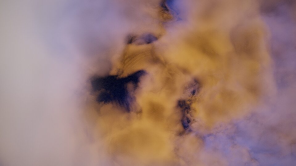
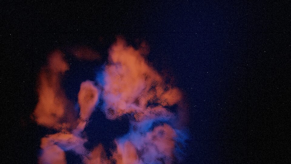
In part 1 we got an empty macOS window and a timeline(t) function that describes the script. Today the window comes alive: by the end of this article it shows a nebula with a camera flying through it. We go in small steps, and every step has a picture: each frame below was rendered by the real shader at that stage.
How a frame reaches the screen
First the big picture. The whole frame is drawn by one program on the GPU, the fragment shader. It runs once for every pixel, independently and in parallel: about a million times per frame at 1280×720. The CPU only prepares eight parameter numbers and says “draw”.
Step 1. Metal and MTKView
MTKView is a ready-made MetalKit view that holds a “canvas” for Metal and calls us 60 times a second [1]. To create it we need a device, that is, the GPU:
src/main.rs
let device = MTLCreateSystemDefaultDevice().expect("Metal device unavailable");

let view = MTKView::initWithFrame_device(MTKView::alloc(mtm), rect, Some(&device));
1view.setColorPixelFormat(MTLPixelFormat::BGRA8Unorm_sRGB);
2view.setAutoResizeDrawable(false);
view.setPreferredFramesPerSecond(60);
window.setContentView(Some(&view));- 1
- The shader computes color in linear space, and the hardware applies the sRGB encoding when it writes the pixel. Blending and fades then behave physically correctly.
- 2
- We set the canvas size ourselves (see step 2): rendering a nebula at the Retina resolution of 2560×1440 is pointless, and it would cost four times as much.
The window still looks empty, but now the GPU lives inside it.
Step 2. A delegate and the first color
MTKView does not know what to draw. Every 16.6 ms it asks its delegate, an object with a drawInMTKView: method. With objc2, such an Objective-C class is declared right in Rust:
src/main.rs (abridged)
define_class!(
    #[unsafe(super(NSObject))]
    #[thread_kind = MainThreadOnly]
    #[ivars = Ivars]                 // our state: command queue, pipeline, clock
    struct Renderer;

    unsafe impl MTKViewDelegate for Renderer {
        #[unsafe(method(drawInMTKView:))]
        fn draw_in_mtk_view(&self, view: &MTKView) {
            self.draw(view);
        }
        // ...
    }
);
sequenceDiagram
participant V as MTKView
participant R as Renderer
participant G as GPU
loop every 16.6 ms
V->>R: drawInMTKView(view)
R->>R: t → Params
R->>G: commandBuffer: setPipeline, setBytes, draw 3 vertices
R->>G: presentDrawable, commit
G-->>V: the finished frame on screen
end
The frame itself is a list of commands written into a buffer and sent to the GPU:
src/main.rs
let Some(pass) = view.currentRenderPassDescriptor() else { return };
let Some(drawable) = view.currentDrawable() else { return };
let Some(cmd) = iv.queue.commandBuffer() else { return };
let Some(enc) = cmd.renderCommandEncoderWithDescriptor(&pass) else { return };

enc.setRenderPipelineState(&iv.pipeline);
unsafe {
    enc.drawPrimitives_vertexStart_vertexCount(MTLPrimitiveType::Triangle, 0, 3);
}
enc.endEncoding();
cmd.presentDrawable(ProtocolObject::from_ref(&*drawable));
cmd.commit();
To have something to draw, we need a pipeline: a pair of shaders, vertex and fragment, compiled for the canvas format. We do not ship the shader as a separate file; we embed it as text in the binary and let the driver compile it at startup. That is also the first step towards compression later: text compresses very well.
src/main.rs (abridged)
const SHADER: &str = include_str!("star_fabric.metal");

let library = device
    .newLibraryWithSource_options_error(&NSString::from_str(SHADER), None)
    .unwrap_or_else(|e| panic!("shader compile failed:\n{}", e.localizedDescription()));
let vs = library.newFunctionWithName(ns_string!("vs")).expect("no vs");
let fs = library.newFunctionWithName(ns_string!("fs")).expect("no fs");
Shaders are written in the Metal Shading Language, a dialect of C++ [2]. The very first fragment shader just returns a constant:
star_fabric.metal (stage 1)
fragment float4 fs(VOut in [[stage_in]]) {
    return float4(0.05, 0.08, 0.22, 1.0);   // linear color: looks lighter on screen
}
Step 3. One triangle for the whole screen
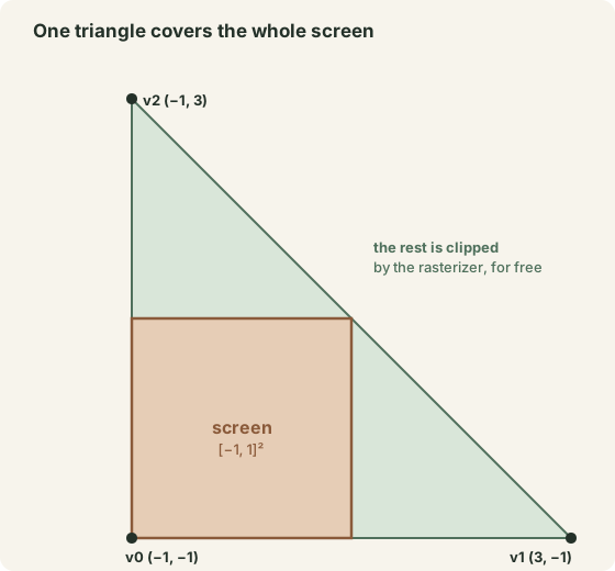
The fragment shader only runs for pixels covered by geometry. A classic demoscene trick: instead of a rectangle made of two triangles, draw one big triangle that is guaranteed to cover the screen. The vertices do not even need to be passed in; they can be computed from the vertex index:
star_fabric.metal
vertex VOut vs(uint id [[vertex_id]]) {
    float2 p = float2((id << 1) & 2, id & 2);  // (0,0), (2,0), (0,2)
    VOut o;
    o.pos = float4(p * 2.0 - 1.0, 0.0, 1.0);   // (-1,-1), (3,-1), (-1,3)
    return o;
}
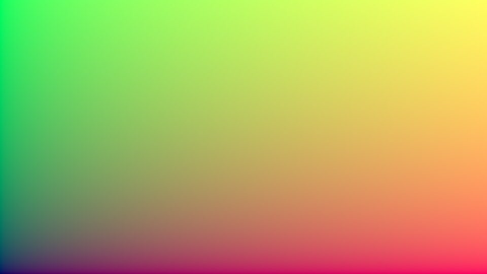
Now every pixel knows its coordinates. We normalize them and output them as a color:
star_fabric.metal (stage 2)
fragment float4 fs(VOut in [[stage_in]], constant Params& P [[buffer(0)]]) {
    float2 uv = in.pos.xy / P.res;
    return float4(uv.x, 1.0 - uv.y, 0.5 + 0.5 * sin(P.time), 1.0);
}
Step 4. Frame parameters
How does the shader know the time and the resolution? Every frame the CPU passes it a small struct. Its memory layout must match byte for byte on both sides:
src/main.rs
#[repr(C)]                       // C layout, no field reordering
struct Params {
    res: [f32; 2],               // canvas size in pixels
    time: f32,                   // seconds since the start
    cam_z: f32,                  // where the camera is on its path
    phase: f32,                  // continuous scene index 0…4
    fade: f32,                   // master brightness
    core_z: f32,                 // where the core star is
    beat: f32,                   // kick drum hit (part 6)
}
star_fabric.metal
struct Params {
    float2 res;
    float  time;
    float  cam_z;
    float  phase;
    float  fade;
    float  core_z;
    float  beat;
};  // 8 × 4 = 32 bytes; float2 is 8-aligned, like [f32; 2] as the first field
src/main.rs
enc.setFragmentBytes_length_atIndex(
NonNull::from(¶ms).cast(),
size_of::<Params>(), // 32
0, // [[buffer(0)]] in the shader
);Data this small needs no buffer: setFragmentBytes copies up to 4 KB straight into the command.
Step 5. A ray from the camera
Now the key transition, from a flat picture to 3D. Every pixel is a direction the camera looks in. Through each pixel we cast a ray \mathbf{r}(s) = \mathbf{o} + s\,\mathbf{d} and ask what it meets along the way.
The camera flies along a winding path and looks at a point slightly ahead. The view direction and the roll give a basis (\mathbf{u}, \mathbf{v}, \mathbf{w}), and the ray direction for a pixel at (x, y) is
\mathbf{d} = \operatorname{normalize}\left(x\,\mathbf{u} + y\,\mathbf{v} + f\,\mathbf{w}\right)
where f is the “focal length”: the larger it is, the narrower the field of view.
star_fabric.metal
float2 path(float z) {   // the flight path: a smooth snake
    return float2(sin(z * 0.11) * 2.5 + sin(z * 0.037) * 4.0, cos(z * 0.083) * 1.8);
}

float3 ro = float3(path(P.cam_z), P.cam_z);               // the camera on its path
float3 ta = float3(path(P.cam_z + 4.0), P.cam_z + 4.0);   // looking 4 units ahead
float  roll = 0.15 * sin(P.time * 0.13) + s.twist * 0.8 * sin(P.time * 0.4);
float3 cw = normalize(ta - ro);
float3 cu = normalize(cross(cw, float3(sin(roll), cos(roll), 0.0)));
float3 cv = cross(cu, cw);
float3 rd = normalize(uv.x * cu + uv.y * cv + s.fov * cw);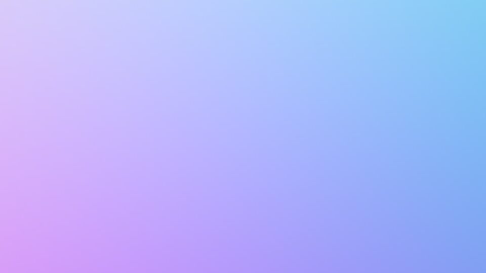
Step 6. Noise and gas density
A nebula is a density field: a function that says how much gas there is at any point in space. Noise makes it look like clouds.
Value noise works like this: random numbers sit at the nodes of an integer lattice (a hash function of the coordinates provides them), and the values in between are interpolated smoothly. This is the first, “honest” version: eight hashes per sample.
star_fabric.metal (first version of the noise)
float hash(float3 p) {                      // a pseudorandom number from coordinates
    p = fract(p * 0.3183099 + 0.1);
    p *= 17.0;
    return fract(p.x * p.y * p.z * (p.x + p.y + p.z));
}

float noise(float3 x) {
    float3 i = floor(x), f = fract(x);
    f = f * f * (3.0 - 2.0 * f);            // smoothstep: no creases at cell edges
    return mix(mix(mix(hash(i + float3(0,0,0)), hash(i + float3(1,0,0)), f.x),
                   mix(hash(i + float3(0,1,0)), hash(i + float3(1,1,0)), f.x), f.y),
               mix(mix(hash(i + float3(0,0,1)), hash(i + float3(1,0,1)), f.x),
                   mix(hash(i + float3(0,1,1)), hash(i + float3(1,1,1)), f.x), f.y), f.z);
}
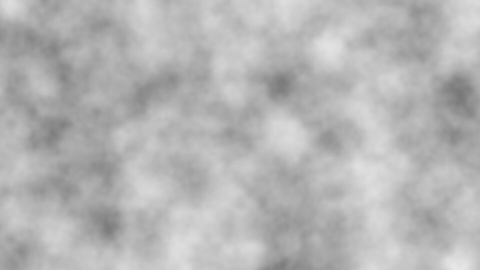
One layer of noise is too smooth. Clouds need detail at every scale, so we add several octaves, each twice as fine and half as strong. That is fbm, fractional Brownian motion [3]:
\operatorname{fbm}(\mathbf{p}) = \sum_{k=0}^{3} \frac{1}{2^{k+1}}\; n\!\left((2.03\,M)^k\,\mathbf{p}\right)
The rotation matrix M between octaves hides the lattice: without it the eye catches on repeating axes.
star_fabric.metal
constant float3x3 kOct = float3x3(float3( 0.00,  0.80,  0.60),
                                  float3(-0.80,  0.36, -0.48),
                                  float3(-0.60, -0.48,  0.64));
float fbm(float3 p) {
    float s = 0.0, a = 0.5;
    for (int i = 0; i < 4; i++) {
        s += a * noise(p);
        p = kOct * p * 2.03;
        a *= 0.5;
    }
    return s;
}
From noise we make density. All the artistic decisions live here, so let us go line by line:
star_fabric.metal
float density(float3 p, thread const Scene& s, thread float& tint, thread float& dark) {
1    float2 q = p.xy - path(p.z);
2    q = rot(s.twist * 4.0 * sin(p.z * 0.13)) * q;
    float r = length(q);

    float3 w  = float3(q, p.z);
    float  wn = noise(w * 0.17 + float3(0.0, 0.0, s.t * 0.03));
3    tint = wn;
4    w += (wn - 0.5) * 4.0;

    float n = fbm(w * 0.33);
5    dark = smoothstep(0.62, 0.80, n);

6    float d = (n - 0.5) * 4.0 * s.dens;
7    d *= smoothstep(0.7, 2.8, r);
8    d *= 1.0 - smoothstep(5.0, 11.0, r);
9    d *= smoothstep(14.0, 24.0, p.z + wn * 8.0);
    return max(d, 0.0);
}- 1
- Coordinates relative to the camera path: everything below is computed “around the flight line”.
- 2
- A twist around the path axis. It is strong in the “flow” scene and almost zero elsewhere.
- 3
- A large, slow noise also decides whether the gas is warm or cool (the color comes in step 8).
- 4
- Domain warping: the coordinates are displaced by noise, and the clouds become ragged and fluid [4].
- 5
- Where fbm peaks, there will be dense dark dust.
- 6
- A threshold: gas exists only where the noise is above 0.5. That creates gaps and voids.
- 7
- A corridor of about 2 units around the path stays clear, or the camera would fly through a wall.
- 8
- Beyond a radius of 11 the gas ends: the cloud is a finite tube, not infinite cotton wool.
- 9
- The cloud starts ahead of the camera. The noise makes its edge ragged, so in the first scene the nebula drifts out of the darkness.
Step 7. Marching through the volume
Gas is not a surface, and a ray does not “hit” it. So we walk along the ray in small steps and ask for the density at each point. Every layer of gas adds light (emission) and hides what lies behind it (absorption). This is the classic emission–absorption model [5].
The quantity that ties it together is the transmittance T: the fraction of light from deeper in that still reaches the camera. It starts at T = 1 and drops with every layer:
a_i = 1 - e^{-d_i\,\Delta s_i}, \qquad C \mathrel{+}= T_i\, a_i\, \mathbf{e}_i, \qquad T_{i+1} = T_i\,(1 - a_i)
where d_i is the density, \Delta s_i the step length, and \mathbf{e}_i the color the gas emits at that point.
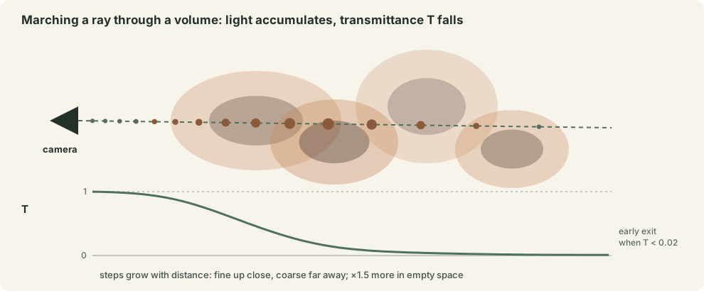
star_fabric.metal (abridged)
float dither = fract(52.9829189 * fract(dot(px, float2(0.06711056, 0.00583715))));
float3 col = 0.0;
float  T   = 1.0;
1float  tt  = 0.05 + 0.25 * dither;

for (int i = 0; i < 64; i++) {
    float3 p = ro + rd * tt;
    float  tint, dark;
    float  d  = density(p, s, tint, dark);
2    float  st = 0.12 + tt * 0.045;
    if (d > 0.0) {
        float3 base = mix(s.cool, s.warm, smoothstep(0.3, 0.7, tint));
        float  rim  = smoothstep(0.0, 0.15, d) * (1.0 - 0.7 * smoothstep(0.15, 0.8, d));
3        float3 e = base * (0.03 + 0.45 * rim) * (1.0 - 0.9 * dark);
        float a = 1.0 - exp(-d * st);
        col += T * a * e;
        T   *= 1.0 - a;
4        if (T < 0.02) break;
    } else {
5        st *= 1.5;
    }
    tt += st;
    if (tt > 45.0) break;
}- 1
- Each pixel starts its ray slightly offset, following interleaved gradient noise [6]. Without it, 64 steps produce visible “slices”; with it, the slices become fine grain the eye does not notice.
- 2
- The step grows with distance: detail matters up close, not far away. 64 steps cover 45 units of depth.
- 3
-
The key artistic idea: thin gas glows, dense cores go dark. Emission peaks at cloud edges, and dust (
dark) dims it by 90%. The result is glowing outlines and dark “pillars”, as in photographs of real nebulae. - 4
- Early exit: once the transmittance is nearly used up, nothing further is visible.
- 5
- In empty space, step one and a half times faster.
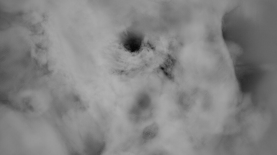
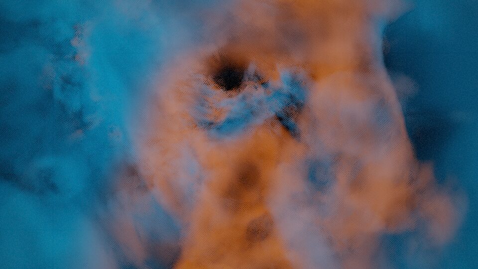
To see the shape without the distraction of color, we first render the volume in gray, then with the palette:
Step 8. The core star and the starry sky
In the “core” scene a star burns inside the nebula. It does three things:
- it lights the gas around it, falling off with the square of the distance:
lit = core * 1.2 / (1 + |L|² · 0.5); - it glows itself: a bright point with a soft halo, computed from the angular distance between the ray and the star;
- it is occluded by gas: its light is multiplied by the transmittance T at the moment the ray passes it.
star_fabric.metal
// Core star: point + halo, occluded by the gas in front of it.
float ang = length(sp - rd * max(tc, 0.0)) / max(tc, 0.1);   // angle between the ray and the star
float g   = s.core * step(0.0, tc) * Tstar;                   // only ahead, attenuated by gas
col += float3(1.0, 0.85, 0.6) * g * (0.0003 / (ang * ang + 0.00004) + 0.2 * exp(-ang * 10.0));
Background stars are cheap: the ray direction is split into cells, and in a rare cell, chosen by a hash, a point lights up. Three layers with different densities, plus twinkling from sin(t). The stars are also multiplied by the remaining transmittance T, so they are not visible through dense gas.
Step 9. Post-processing
Accumulated light easily exceeds 1, while the screen only shows 0…1. Tone mapping compresses the bright parts gently instead of clipping them. We use a popular approximation of the ACES curve [7]:
\operatorname{ACES}(x) = \operatorname{saturate}\!\left(\frac{x\,(2.51x + 0.03)}{x\,(2.43x + 0.59) + 0.14}\right)
star_fabric.metal
col  = aces(col * P.fade * (1.3 + 0.35 * P.beat));     // exposure; beat comes in part 6
col *= 1.0 - 0.45 * dot(uv, uv);                       // vignette
col += (hash(float3(px, fract(P.time) * 61.0)) - 0.5) * 0.015;  // film grain
return float4(max(col, 0.0), 1.0);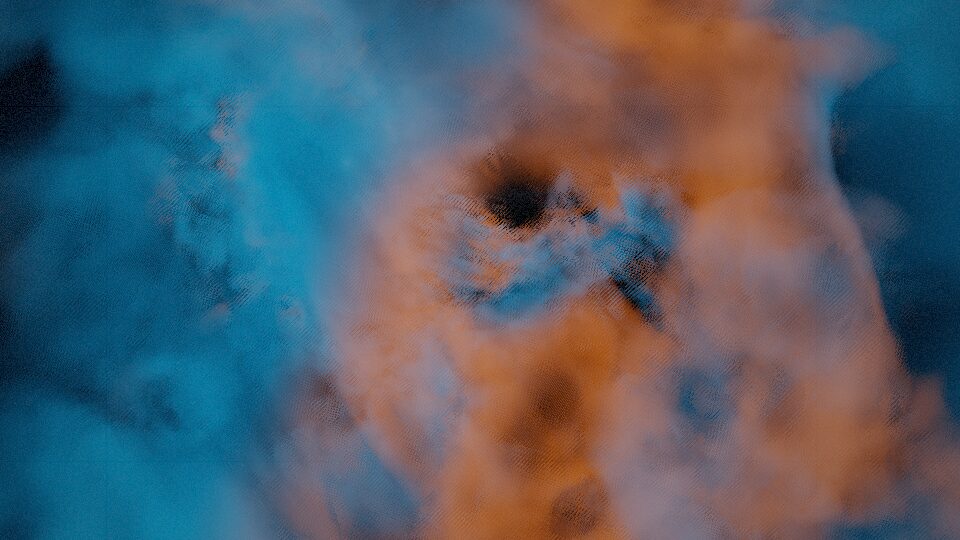
Step 10. Scenes and flight over time
What remains is tying the shader to the script. Each of the five scenes has its own parameters: gas density, star strength, twist, field of view, star brightness, two palettes. The shader takes the continuous phase from part 1 and blends adjacent rows of the tables:
star_fabric.metal (abridged)
constant float  kDens [5] = { 0.70, 1.00, 1.15, 0.90, 0.35 };   // gas density
constant float  kCore [5] = { 0.00, 0.15, 1.00, 0.20, 0.00 };   // star strength
constant float  kTwist[5] = { 0.00, 0.10, 0.15, 0.70, 0.20 };   // twist of the "flow"
constant float  kFov  [5] = { 1.80, 1.60, 1.50, 1.10, 1.70 };   // wider angle = more speed
// ... kStars, kWarm, kCool

template <typename T>
T pick(constant T* a, float ph) {        // phase = 2.4 → 60% scene 2 + 40% scene 3
    int i = min(int(ph), 3);
    return mix(a[i], a[i + 1], ph - float(i));
}
The camera moves along the path, and there is a subtlety. The camera position is the integral of its speed, and the speed differs between scenes. Adding speed × dt every frame would make the path depend on the frame rate, and the demo would fall behind on a slow machine. So the position is a function of time, integrated with a fixed step:
z(t) = z_0 + \int_0^t v(\tau)\,d\tau \approx z_0 + \sum_{k} v\!\left((k + \tfrac12)h\right) h, \qquad h = \tfrac{1}{32}\text{ s}
src/lib.rs
pub fn camera_speed(time: f32) -> f32 {        // speed changes smoothly at scene boundaries
    let mut s = SPEEDS[0];
    for i in 1..SPEEDS.len() {
        s += (SPEEDS[i] - SPEEDS[i - 1]) * smoothstep(SCENES[i] - 2.0, SCENES[i] + 2.0, time);
    }
    s
}

pub fn camera_z(time: f32) -> f32 {
    const H: f32 = 1.0 / 32.0;
    let t = clamp(time, 0.0, DEMO_DURATION);
    let n = (t / H) as u32;
    let mut z = START_Z;                        // start far in front of the cloud
    for k in 0..n {
        z += camera_speed((k as f32 + 0.5) * H) * H;
    }
    let rem = t - n as f32 * H;
    z + camera_speed(t - rem * 0.5) * rem
}
A test checks that the camera always moves forward without jumps, frame by frame at 60 fps:
src/lib.rs
#[test]
fn camera_moves_forward_smoothly() {
    let mut prev = camera_z(0.0);
    let mut t = 0.0;
    while t < DEMO_DURATION {
        t += 1.0 / 60.0;
        let z = camera_z(t);
        assert!(z > prev);
        assert!(z - prev < 0.06, "jump at t={t}");
        prev = z;
    }
}
Summary
| Step | What appeared | Key idea |
|---|---|---|
| 1–2 | MTKView, delegate, pipeline | The GPU draws, the CPU only gives orders |
| 3 | Fullscreen triangle | A fragment shader is a “function of the pixel” |
| 4 | Params | Identical struct layout in Rust and Metal |
| 5 | Camera ray | A pixel is a direction in 3D |
| 6 | Noise, fbm, density | Clouds from a threshold and warped noise |
| 7 | Volume march | Transmittance T, emission, early exit |
| 8–9 | Star, stars, tone mapping | Light occluded by gas |
| 10 | Scenes and camera | Everything is a function of time |
WarningTwo problems we have hidden so far
The pictures in this article are the result of long tuning. The first version looked nothing like them: overexposed cotton wool filling the whole screen. Part 3 tells how we fixed it. The second problem is speed. With the “honest” hash noise, an M1 cannot reach 60 frames per second at 720p, and part 4 shows how to make the noise 2.3 times faster.
Series: Demoscene 2026
Part 2 of 7 · suggested reading order
Previous: The demoscene in 2026: why write a 64k intro in Rust on macOS
Next: Six iterations to a picture: debugging a shader without a screen
References
[1]
Apple Inc. MTKView. https://developer.apple.com/documentation/metalkit/mtkview
[2]
Apple Inc. Metal Shading Language Specification. https://developer.apple.com/metal/Metal-Shading-Language-Specification.pdf
[3]
Quilez I. fBM. 2019. https://iquilezles.org/articles/fbm/
[4]
Quilez I. Domain warping. 2002. https://iquilezles.org/articles/warp/
[5]
Max N. Optical models for direct volume rendering. IEEE Transactions on Visualization and Computer Graphics. 1995. DOI: 10.1109/2945.468400
[6]
Jimenez J. Next Generation Post Processing in Call of Duty: Advanced Warfare. 2014. https://www.iryoku.com/next-generation-post-processing-in-call-of-duty-advanced-warfare
[7]
Narkowicz K. ACES Filmic Tone Mapping Curve. 2016. https://knarkowicz.wordpress.com/2016/01/06/aces-filmic-tone-mapping-curve/